
When infrastructure teams move workloads from a managed cloud to bare metal, they often carry a hidden assumption with them: that the network is someone else’s problem. On AWS or Azure, it largely was. Virtual NICs, managed load balancers, and software-defined fabrics abstracted away every cable, every switch port, every failover decision. On bare metal, none of that abstraction exists by default. You are back to real hardware, real topology choices, and real consequences when something goes wrong at 3 a.m.
This is not a problem. It is an opportunity to build a network that is actually sized for your traffic, not padded for a provider’s margin. But it requires vocabulary and a decision framework that cloud-native defaults never forced you to develop. That framework starts with understanding the homing spectrum.
The homing spectrum: four canonical positions
Every bare metal network topology sits somewhere on a spectrum defined by two variables: how many upstream providers you connect to, and how many physical links you use per provider. The four canonical positions are:
- Single-homed: one link to one provider. Simple and cheap; a single cable or transceiver failure takes you offline.
- Dual-homed: two or more links to a single provider. You gain link-level redundancy but remain dependent on one upstream. A provider-side outage still kills connectivity.
- Single multi-homed: one link each to two or more different providers. Provider diversity is good; a single router on your side is still a failure point.
- Dual multi-homed: two or more links to two or more providers. Maximum resilience, maximum complexity, and the highest cost. Reserve it for traffic paths where downtime has a direct revenue or safety consequence.
Most bare-metal deployments land between dual-homed and dual multi-homed depending on their SLA requirements and budget. The goal is to match the topology to the actual risk, not to replicate whatever the cloud provider was doing underneath the abstraction layer.
NIC bonding: active-passive vs. LACP
At the server level, dual-homing means connecting a server to two independent upstream switch ports. The operating system sees this as two physical interfaces, and you need to decide how to present them to applications. That decision is the bonding mode.
Active-backup (Mode 1) keeps one interface live and parks the other as a hot standby. The OS monitors the primary; if it goes down, it promotes the backup. Failover is clean and predictable. The tradeoff is that you are paying for two uplinks but using only one at a time, which is fine if your goal is pure redundancy rather than throughput.
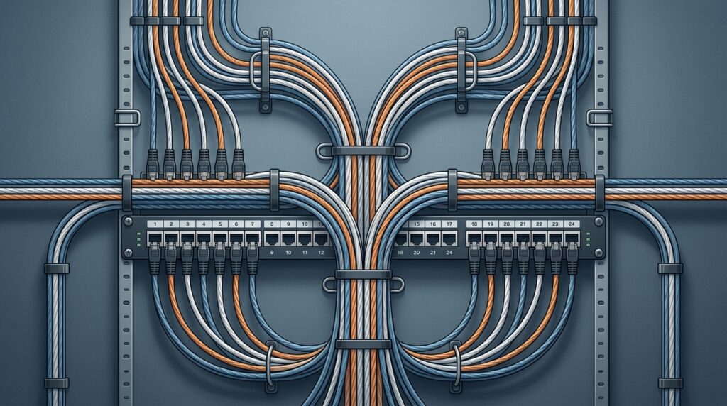
LACP (Mode 4, IEEE 802.1AX) bundles both interfaces into a single logical interface and spreads flows across them. From the application’s perspective there is one network path; from the switch’s perspective there are two. This gives you aggregate capacity across flows, but it does not give any single TCP connection more bandwidth than one member link, because the hardware hashes per flow to pick a member. Knowing this matters for workloads with a small number of high-throughput flows: bonding will not help them the way it helps workloads with many parallel connections.
Link aggregation gives the fabric more capacity and a survivable path. It does not give any single conversation more bandwidth than one member link. Size your uplinks for your actual flow profile, not for the aggregate number on the spec sheet.
A known failure mode worth flagging: dual-homed servers with misconfigured bonding can drop packets during NIC failover. LACP relies on protocol-level keepalives between the NIC and the switch; if those timers are misconfigured or the switch does not support fast LACP timers, the bond can take several seconds to reconverge. Test failover under load before you rely on it.
MC-LAG: eliminating the single-switch failure point
Classic LACP bundles ports on a single physical switch. That means the switch itself is a single point of failure, which defeats much of the redundancy you built at the NIC level. Multi-Chassis LAG (MC-LAG) solves this by allowing two physical switches to coordinate and present themselves as a single LAG partner to the downstream server. The server bonds its two NICs as if they were talking to one switch; in reality, each NIC connects to a separate physical device. A full switch failure now removes one member from the bond rather than taking the server offline.
MC-LAG is the standard pattern for production bare-metal racks where switch-level redundancy matters. The operational cost is that the two switches must maintain a synchronisation channel, and the failure modes of that channel need to be understood and tested. Split-brain scenarios, where both switches believe the other has failed, require a defined tie-breaking policy.
BGP multihoming on bare metal: when to go there
For bare metal network redundancy at the routing layer, BGP multihoming is the mechanism that lets you connect to multiple upstream providers and have traffic automatically shift when one path degrades. This is distinct from link-level bonding: BGP operates at Layer 3 and can route around provider failures, not just cable failures.
The modern data-center approach pushes this further. Instead of bundling uplinks between a leaf switch and a spine, many operators run a separate Layer 3 link to each spine with one BGP session per link. This keeps every path individually visible to the routing protocol, removes LACP from the uplink entirely, and allows the fabric to converge on individual link state rather than waiting for a bundle threshold. The rule of thumb: use ECMP where paths are routed and independent; reserve LAG for places where a single logical interface genuinely simplifies the design, such as a server dual-homing to a switch pair or a Layer 2 trunk.
Carrier-neutral datacenters are what make BGP multihoming practical without overprovisioning. At a carrier-neutral site you can connect to multiple transit providers and exchange routes directly with peers, which means you are not buying redundancy through a single carrier’s infrastructure. We operate our sites on exactly this basis: Tier III, carrier-neutral, ISO 27001 certified, with a contractual 99.9% uptime SLA that reflects the physical redundancy built into the facility itself, not a marketing line layered on top of a single-carrier uplink. Sovereignty, here, is a contract-level guarantee: your traffic paths are governed by European law and do not transit infrastructure subject to foreign jurisdiction.
The decision framework: matching topology to risk
Overprovisioning in bare-metal networking usually comes from applying a maximum-redundancy template to every server regardless of its actual role. A decision framework based on failure impact avoids this:
- Classify the workload by failure cost. A database primary failing over has a different cost profile than a batch processing node. Match the topology tier to that cost, not to a blanket policy.
- Identify the actual failure modes. NIC failure, cable failure, switch failure, and provider failure are distinct events with different probabilities. Design for the ones that are plausible at your scale, not for theoretical worst cases.
- Choose the minimum topology that covers your identified failure modes. Active-backup bonding covers NIC and cable failure. MC-LAG adds switch failure. BGP multihoming adds provider failure. Each layer adds cost and operational complexity; add it only when the failure mode it covers is in scope.
- Test convergence under load. LACP failover, BGP reconvergence, and MC-LAG split-brain recovery all have timing characteristics that only become visible under real traffic. Measure them in staging before you rely on them in production.
- Document the topology explicitly. Cloud-native teams often have no topology documentation because the provider abstracted it. On bare metal, the topology is yours. A diagram showing every uplink, bonding mode, and BGP session is operational infrastructure, not optional paperwork.
What this looks like in practice
A typical production rack on a carrier-neutral site might look like this: servers dual-homed with LACP Mode 4 bonds to a pair of top-of-rack switches running MC-LAG, those switches uplinked via separate Layer 3 paths to a spine layer running ECMP, and the spine connected to two or more transit providers via BGP. That design covers NIC, cable, switch, and provider failure without duplicating every component. It is not the cheapest possible design, but it is not the most expensive either. It is sized for the actual failure modes.
The teams that overbuild are usually the ones who inherited a cloud-native mental model where redundancy was invisible. Once you can see the topology and name each layer’s failure mode, you can make deliberate choices instead of defensive ones. That is the shift bare metal demands, and the reason it rewards engineers who take the time to learn the vocabulary.